Double click image to zoom in


Click image to open expanded view


A DIY soldering kit for an FM radio based on the RDA5807 tuner and an LCD1602 display. After assembly it sits in a clear acrylic enclosure with a telescopic antenna and a rear speaker, as shown on the product images. It is intended as a soldering practice / electronics learning project.
Key Features
- RDA5807 FM radio – adjustable receiving frequency 87–108 MHz (87.0–108.0 MHz on the parameter table).
- LCD1602 display – the assembled example shows “STEREO RADIO”, frequency, and volume.
- LED spectrum indicator – a row of LEDs above the display; the right button turns the indicator on or off.
- Front controls – power switch, volume + / −, frequency + / −, and indicator switch, labeled on the product image.
- Acrylic case and speaker – clear enclosure with a speaker mounted on the back.
Specifications
The following figures are taken from the “Product Parameters” table on the product images:
| Product name | DIY soldering kit for RDA5807 FM radio with LCD display |
|---|---|
| Product model | TJ-56-634 |
| Working voltage | DC 4.5 V–5.5 V |
| Output impedance | 4 Ω |
| Output power | 5 W |
| Output channel | Mono |
| Receiving frequency | 87.0 MHz–108.0 MHz |
| Frequency step | 0.1 MHz |
| Equivalent noise | ≥ 30 dB |
| Enclosure dimensions | 90 × 70 × 55 mm |
The schematic on the product images also shows an STC89C52 microcontroller, the RDA5807 tuner, LCD1602, and an LM386 audio section.
How to use (from the product image)
- Press the left button to turn power on or off.
- Press the right button to turn the spectrum indicator on or off.
- Press S+ or S− to adjust the volume.
- Press P+ or P− to adjust the receiving frequency / FM stations.
Package Contents
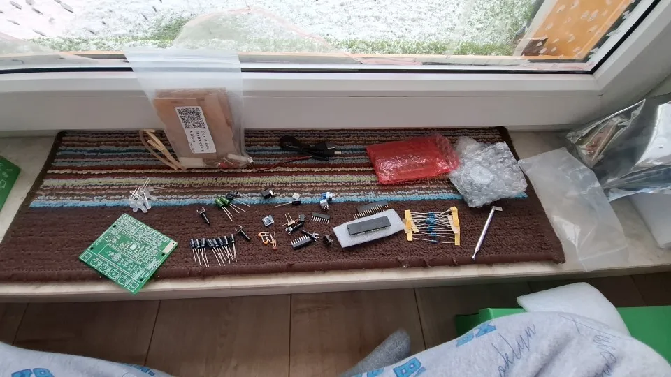
- 1 × DIY FM radio soldering kit with PCB, LCD1602, RDA5807-related parts, acrylic enclosure, telescopic antenna, and speaker, as shown in the product images (unsoldered kit for assembly)
Notes
- This is a soldering practice kit. The photos of the finished radio show the assembled result.
- Power is applied through the side DC jack visible in the photos; a power adapter is not shown as a listed accessory.